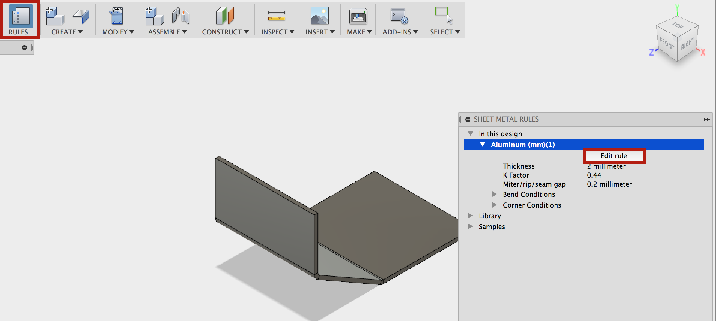
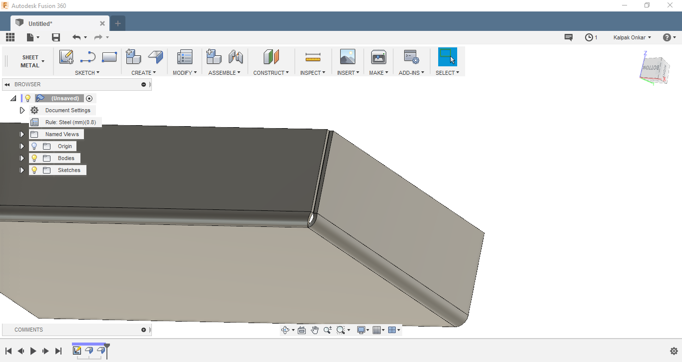
Changing Sheet Metal Thickness In Fusion 360

Fusion 360 Sheet Metal Create Rule And Change Thickness Basic Tutorial Youtube
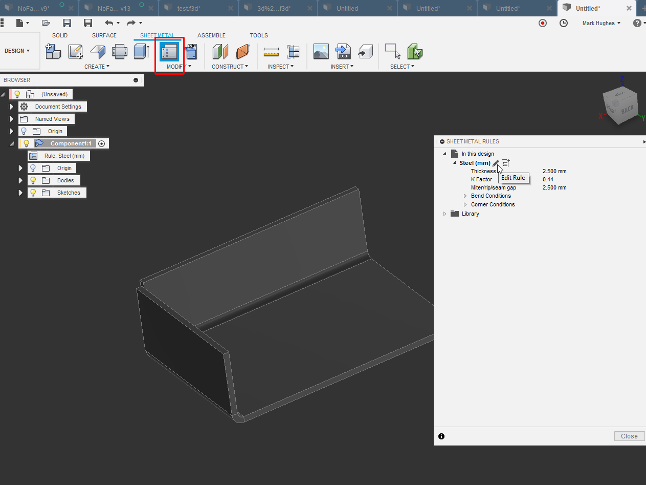
Solved Sheet Metal Rules Unable To Change Thicknes Autodesk Community Fusion 360

Solved Sheet Metal Thickness Parametric Autodesk Community Fusion 360
Solved Change Sheet Metal Rules Mid Stream Autodesk Community Community Archive Read Only

Solved Change Sheet Metal Bend Radius Autodesk Community Inventor

Auto Detecting Sheet Metal Thickness New In Autodesk Inventor 2016 Youtube

Fusion 360 has all the necessary tools to specify different rules for your sheet metal parts thickness bend radius corner relief etc now here is the fun part actually making some sheet metal.
Changing sheet metal thickness in fusion 360.

Sheet Metal Unfold Flat Pattern Isnt The Same Irl Settings Autodesk Community Fusion 360

Solved Help With Flat Pattern From Step File Autodesk Community Inventor

Tutorial 9 Sheet M

Flatten Sheetmetal Cone Autodesk Community Fusion 360

Fusion 360 Sheet Metal Settings And What Is Available

Solved Changing To A Different Sheet Metal Rule Autodesk Community Fusion 360

Conical Bend In Sheet Metal Autodesk Community Fusion 360

Sheet Metal Bend Radius Unfold Table Autodesk Community Inventor

Fusion 360 Ideastation Archived Autodesk Community
Https D1ozhi4p59900 Cloudfront Net Files Urn Adsk Content Library 78756fcf E6f3 4184 Abdd 04afc0337a02 Classhandoutmfg225530sheetmetallikeaprowithfusion360robertsavage Pdf Expires 1609459199 Signature Dbexzkreykgvg Pbvjgrnj3gikkghyfnuolx2gunye Ugz7w2jw7rqxoeiyfibixywrsimdkfyntux51tdxlmmvfg3cksxtob1cqx9hyp37 Dpdf5egb Oe97szbiezko8t1zm6rqgun1ycetg 3d8f27k3jcetam61ejyznymymx0gsr Ao64p1suybv1ed50wu3hevbifcwicvlks4g1eyx4k4sjrowicn2towuuylfiw8wjnmfbn153wqq8zjrxzih4ntgbbthicfcunip5ljdsyf5 Dek4qil9lkwhka2mqflbxuxu3 8cza294kkliu5facj Nsm54dzjuluw Key Pair Id Apkaia22nyyfu6jzr5za

Changing Sheetmetal Kfactor And Bendradius With Ilogic Autodesk Community Inventor
Ignnb710ihxbdm
Solved Convert A Hollow Solid Part To Sheet Metal Flat Pattern S Autodesk Community Inventor

Calculate Material Usage For Sheet Metal Projects Autodesk Community Inventor

Solved Sheetmetal Autodesk Community Inventor

Video Tip Fusion 360 Custom Sheet Metal Rules Youtube
Sheetmetal Corner Seam Tool Autodesk Community Fusion 360

Multi Body Sheet Metal Multi Thickness Autodesk Community Inventor
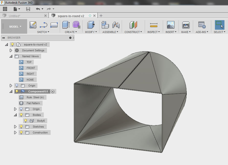
Square To Round Transition Sheet Metal Page 2 Autodesk Community Fusion 360

Sheet Metal Convert Solid To Sm Autodesk Community
Creating Conical Sheet Metal Components In Autodesk Fusion 360
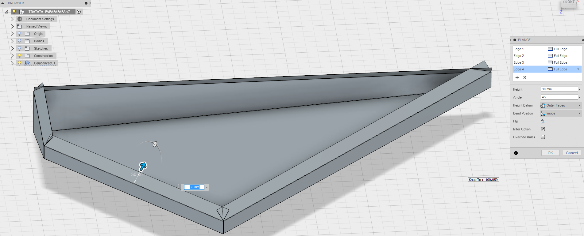
Solved Sheet Metal Flange Miter With Angle Autodesk Community Fusion 360

Solved Unable To Change Sheet Metal Rule Autodesk Community Fusion 360

Solved Sheet Metal Bend Allowance Autodesk Community Inventor
Source : pinterest.com
